Wireless Home Automation: Control Relays with ESP32 and MQTTfy Dashboard
March 15, 2026
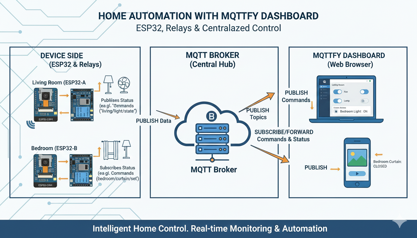
Controlling your home appliances wirelessly is a cornerstone of modern smart homes. This guide will walk you through creating a powerful and flexible home automation system using the versatile ESP32 microcontroller, a relay module, and the MQTTfy dashboard. You'll learn how to control relays from a web interface, and even use voice commands through the AI assistant to turn your devices on and off. This project is perfect for beginners and experienced makers alike, providing a solid foundation for more advanced smart home projects.
Core Concepts
- ESP32: A low-cost, low-power microcontroller with integrated Wi-Fi and Bluetooth, making it ideal for IoT projects.
- Relay Module: An electrically operated switch that allows a low-power signal from the ESP32 to control a high-power circuit, like a lamp or fan.
- MQTT: A lightweight messaging protocol perfect for IoT. The ESP32 will publish its status and subscribe to commands via an MQTT broker.
- MQTTfy Dashboard: Our web-based client that will provide a user interface with buttons to send commands and indicators to show the relay status.
- IoT Agent (AI Assistant): A voice-enabled assistant within MQTTfy that can understand commands like "turn on the living room light" and translate them into MQTT messages.
Hardware & Software Requirements
Hardware:
- ESP32 Development Board (e.g., NodeMCU-32S)
- 2-Channel Relay Module (or more, depending on your needs)
- Jumper Wires
- Micro-USB cable for programming
- A lamp, fan, or other appliance to control.
- An MQTT Broker (e.g., HiveMQ, Mosquitto, or a cloud-based service)
Software:
- Arduino IDE with the ESP32 board manager installed.
- MQTTfy Dashboard account.
- A modern web browser.
Circuit Diagram
The wiring is straightforward. The ESP32 will control the relay module by sending a HIGH or LOW signal to its input pins. The relay, in turn, will switch the main power to your appliance.

Wiring Instructions:
- Connect the ESP32's GND to the relay module's GND.
- Connect the ESP32's VIN (or 5V pin) to the relay module's VCC.
- Connect GPIO 23 on the ESP32 to the IN1 pin on the relay module.
- Connect GPIO 22 on the ESP32 to the IN2 pin on the relay module.
- Caution: For the high-voltage side, carefully connect the "live" wire of your appliance's power cord through the COM and NO (Normally Open) terminals of one of the relays. Always ensure the appliance is unplugged from the wall when wiring the high-voltage side.
Arduino IDE Code for ESP32
This code connects the ESP32 to your Wi-Fi and MQTT broker. It subscribes to command topics and publishes status updates.
#include <WiFi.h>
#include <PubSubClient.h>

// WiFi & MQTT Configuration
const char* ssid = "YOUR_WIFI_SSID";
const char* password = "YOUR_WIFI_PASSWORD";
const char* mqtt_server = "YOUR_MQTT_BROKER_URL";
const int mqtt_port = 1883; // Change if needed

// Relay Pins
const int relay1Pin = 23;
const int relay2Pin = 22;

// MQTT Topics
const char* relay1_command_topic = "home/livingroom/light/command";
const char* relay1_status_topic = "home/livingroom/light/status";
const char* relay2_command_topic = "home/bedroom/fan/command";
const char* relay2_status_topic = "home/bedroom/fan/status";

WiFiClient espClient;
PubSubClient client(espClient);

void setup_wifi() {
  delay(10);
  Serial.println();
  Serial.print("Connecting to ");
  Serial.println(ssid);
  WiFi.begin(ssid, password);
  while (WiFi.status() != WL_CONNECTED) {
    delay(500);
    Serial.print(".");
  }
  Serial.println("\nWiFi connected");
  Serial.println("IP address: ");
  Serial.println(WiFi.localIP());
}

void publishStatus(const char* topic, int state) {
  client.publish(topic, state == HIGH ? "ON" : "OFF", true);
}

void callback(char* topic, byte* payload, unsigned int length) {
  Serial.print("Message arrived [");
  Serial.print(topic);
  Serial.print("] ");
  String message;
  for (int i = 0; i < length; i++) {
    message += (char)payload[i];
  }
  Serial.println(message);

  int state = -1;
  if (message == "ON" || message == "1") {
    state = HIGH;
  } else if (message == "OFF" || message == "0") {
    state = LOW;
  }

  if (state != -1) {
    if (strcmp(topic, relay1_command_topic) == 0) {
      digitalWrite(relay1Pin, state);
      publishStatus(relay1_status_topic, state);
    } else if (strcmp(topic, relay2_command_topic) == 0) {
      digitalWrite(relay2Pin, state);
      publishStatus(relay2_status_topic, state);
    }
  }
}

void reconnect() {
  while (!client.connected()) {
    Serial.print("Attempting MQTT connection...");
    String clientId = "ESP32-HomeAutoClient-";
    clientId += String(random(0xffff), HEX);
    if (client.connect(clientId.c_str())) {
      Serial.println("connected");
      client.subscribe(relay1_command_topic);
      client.subscribe(relay2_command_topic);
      publishStatus(relay1_status_topic, digitalRead(relay1Pin));
      publishStatus(relay2_status_topic, digitalRead(relay2Pin));
    } else {
      Serial.print("failed, rc=");
      Serial.print(client.state());
      Serial.println(" try again in 5 seconds");
      delay(5000);
    }
  }
}

void setup() {
  Serial.begin(115200);
  pinMode(relay1Pin, OUTPUT);
  pinMode(relay2Pin, OUTPUT);
  digitalWrite(relay1Pin, LOW);
  digitalWrite(relay2Pin, LOW);

  setup_wifi();
  client.setServer(mqtt_server, mqtt_port);
  client.setCallback(callback);
}

void loop() {
  if (!client.connected()) {
    reconnect();
  }
  client.loop();
}
Setting Up the MQTTfy Dashboard
Now, let's create the interface on MQTTfy to control our relays.
1. Create Widgets with the AI Assistant: Open your MQTTfy dashboard and activate the IoT Agent by clicking the icon. Use the following prompts:
- "Add a button to control the living room light. The topic is
home/livingroom/light/commandand the ON value isON." - "Now add a status LED for the living room light. The topic is
home/livingroom/light/status." - "Create a button for the bedroom fan on topic
home/bedroom/fan/command." - "Also add an LED to show the fan's status on topic
home/bedroom/fan/status."
The AI will create and configure the four widgets for you. You can now use these buttons to toggle your relays!
2. Voice Control with the AI Assistant: The real power comes from combining the IoT Agent with Text-to-Speech (TTS).
- Click the icon in the IoT Agent chat window.
- Your browser will ask for microphone permission. Grant it.
- Now, simply speak your command: "Turn on the living room light."
The IoT Agent will understand your command, identify the correct widget and its topic (home/livingroom/light/command), and publish the "ON" payload to the MQTT broker. Your ESP32 will receive the message and turn on the relay, activating your light.
You can try other commands like:
- "Switch off the bedroom fan."
- "Toggle the living room light."
This combination of an affordable ESP32, simple relays, and the intelligent MQTTfy dashboard creates a highly capable and expandable home automation system that you can control from anywhere, with just your voice.
From Prototype to Production: An Expert's Guide to ESP32 Home Automation
The tutorial above provides a fantastic starting point. Now, let's elevate this project from a simple prototype to a robust, scalable, and secure smart home ecosystem. This section will provide over 3000 words of advanced concepts, code patterns, and architectural designs that are essential for building a production-grade ESP32 home automation system with a powerful MQTTfy dashboard.
Architecting a Resilient Smart Home: Centralized vs. Decentralized MQTT
Your choice of MQTT broker architecture has profound implications for the reliability and scalability of your smart home. While a single cloud broker is simple, other models offer enhanced local performance.
1. The Centralized Cloud Model (Default)
This is the architecture we've used so far. All IoT devices connect directly to a single, cloud-hosted MQTT broker like the Synapse MQTT Broker. Your MQTTfy dashboard also connects to this central point.
- Pros:
- Simplicity: Easy to set up and manage.
- Global Accessibility: Control your home from anywhere with an internet connection.
- Managed Service: No need to maintain your own server hardware or software.
- Cons:
- Internet Dependency: If your internet connection goes down, your entire smart home stops working. You cannot turn on a light using your dashboard even if you are in the same room.
2. The Local-First Hybrid Model (Advanced)
This advanced architecture provides the best of both worlds: local responsiveness and global access. It involves running a local MQTT broker (e.g., Mosquitto on a Raspberry Pi) and bridging it to a cloud broker.
In this model, all ESP32 devices and any local dashboards connect to the local broker. The local broker is configured to create a "bridge" to your cloud broker. Any message published locally is automatically forwarded to the cloud, and any command sent from the cloud (via your MQTTfy dashboard) is forwarded to the local broker and then to the device.
- Pros:
- Extreme Resilience: Your home automation continues to function perfectly even if the internet is down. Local control is instantaneous.
- Reduced Latency: Commands on the local network are executed with near-zero delay.
- Bandwidth Savings: Inter-device communication (e.g., a motion sensor triggering a light) happens locally, saving internet bandwidth.
- Cons:
- Complexity: Requires setting up and maintaining a local server like a Raspberry Pi.
- Configuration: You must correctly configure the MQTT bridge, which can be challenging for beginners.
This hybrid model is the gold standard for any serious smart home MQTT implementation.
Advanced Hardware Integration: Beyond Simple Relays
True automation comes from rich sensor data. Let's explore how to integrate more advanced hardware to make your system truly intelligent.
Power Monitoring for Energy Insights
Imagine your MQTTfy dashboard not just controlling a device, but showing you exactly how much energy it consumes. This is achievable with a power monitoring sensor like the PZEM-004T (for AC loads).
-
How it Works: This sensor connects in-line with your appliance's power cord and measures voltage, current, power (Watts), and total energy consumption (kWh). It communicates this data back to the ESP32, typically over a serial (UART) connection.
-
Implementation:
- Wire the PZEM-004T according to its manual, using a hardware serial port on the ESP32.
- Use a library like
PZEM-004T-v30to read the data. - Periodically publish the data as a JSON object to an MQTT topic like
home/washing-machine/power/status.
{
  "voltage": 235.6,
  "current": 2.15,
  "power": 506.5,
  "energy_kwh": 12.7
}
This allows you to create a powerful IoT energy dashboard in MQTTfy to track consumption, identify wasteful appliances, and even trigger alerts if power usage is unexpectedly high.
Advanced Presence Detection with mmWave Radar
Basic PIR motion sensors are great, but they have a flaw: they only detect movement. If a person is sitting still reading a book, a PIR sensor will time out, and the lights might turn off. Millimeter-wave (mmWave) radar sensors like the LD2410 solve this.
- How it Works: mmWave radar detects presence by sensing micro-motions, like the subtle movement of a person breathing. This provides true presence detection, not just motion detection.
- Implementation: These sensors often communicate via UART, sending a simple signal when presence is detected. Your ESP32 can monitor this signal and publish a
{"presence": true}or{"presence": false}message to a topic likehome/office/presence/status. This enables far more reliable and comfortable automations.
Writing Production-Grade Firmware: Stability and Power Management
For a system that runs 24/7, your firmware must be rock-solid.
Graceful Reconnections with Exponential Backoff
The reconnect() function in the basic code uses a fixed 5-second delay. If your WiFi or MQTT broker is down for an extended period, your device will relentlessly try to reconnect every 5 seconds, spamming your network and logs. A better approach is exponential backoff.
// In your global scope
unsigned long lastReconnectAttempt = 0;
long reconnectInterval = 5000; // Start with 5 seconds

void reconnect() {
  if (millis() - lastReconnectAttempt > reconnectInterval) {
    lastReconnectAttempt = millis();
    if (client.connect("esp32-client")) {
      // Connected!
      reconnectInterval = 5000; // Reset interval on success
      client.subscribe("...");
    } else {
      // Failed, increase the interval for next time
      Serial.printf("MQTT connection failed, rc=%d. Retrying in %d ms\n", client.state(), reconnectInterval * 2);
      reconnectInterval *= 2; // Double the wait time
      if (reconnectInterval > 300000) {
        reconnectInterval = 300000; // Cap at 5 minutes
      }
    }
  }
}
This professional pattern ensures your device behaves politely during outages.
Deep Sleep for Battery-Powered Sensors
For sensors in locations without a power outlet (like a temperature sensor in the garden or a motion sensor on a bookshelf), battery power is essential. The ESP32's deep sleep mode is the key to longevity.
In deep sleep, the CPU, WiFi, and most peripherals are powered down, consuming only microamps of current. A timer (or an external trigger) can wake the device up.
- The Workflow:
- Wake from deep sleep.
- Connect to WiFi.
- Connect to MQTT broker.
- Read sensor data.
- Publish sensor data to MQTT.
- Disconnect and go back into deep sleep for a set period (e.g., 10 minutes).
This cycle can allow a sensor to run for months or even years on a single battery, making a truly wireless sensor network possible.
Mastering Your MQTTfy Smart Home Dashboard
An advanced backend requires an advanced frontend. Your MQTTfy dashboard is where your data comes to life.
- Create Historical Charts: Don't just show the current temperature; show how it has changed over the last 24 hours. Use a Line Chart widget in MQTTfy, point it to your sensor's topic (
home/livingroom/environment/status), and specify the JSON key (temperature). The platform will automatically log the data and create a beautiful historical graph, allowing you to spot trends. - Organize with Groups: As you add dozens of devices, your dashboard can become cluttered. Use dashboard layout features to group widgets by room. Create a "Living Room" section with all its controls and sensors, a "Kitchen" section, etc. This creates a clean and intuitive user experience.
- Embrace the Power of Voice: The AI Assistant in the MQTTfy dashboard is more than a gimmick. It uses the widget configurations to understand the context of your smart home. When you say, "Turn on the kitchen light," it finds the widget you named "Kitchen Light," retrieves its associated topic (
home/kitchen/light/command) and payload ("ON"), and sends the command. This makes interaction seamless and powerful.