Stream Images from ESP32-CAM to MQTTfy Dashboard via MQTT
March 15, 2026
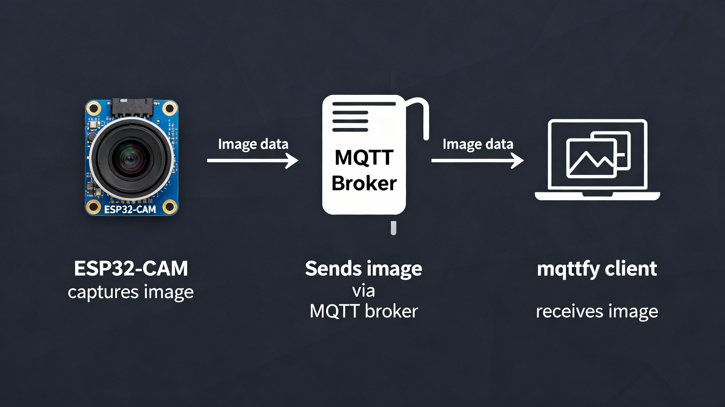
The ESP32-CAM is a powerful, low-cost microcontroller with an integrated camera, making it a perfect choice for a wide range of IoT projects. When combined with the MQTT protocol and a real-time dashboard like MQTTfy, you can create a surprisingly capable live image streaming system for everything from home security and smart agriculture to Industrial IoT (IIoT) applications like remote visual inspection.
This comprehensive guide will walk you through the entire process: setting up your Arduino IDE, programming the ESP32-CAM to capture images, encoding them, and publishing them over MQTT. We'll then show you how to configure an Image Widget in your MQTTfy dashboard to display your live feed. We will also explore advanced topics including performance optimization, alternative architectures, and the critical steps for securing your visual IoT devices.
Core Concepts: Why and How to Send Images over MQTT
To successfully send images, we need to understand the fundamentals of the MQTT protocol. Before diving into the code, let's understand the data flow. The MQTT protocol is fundamentally text-oriented, designed for small, efficient telemetry messages. Sending a binary file like a JPEG image directly is not its primary use case and presents challenges. To solve this, we must encode the image into a text format that can be safely embedded within a standard MQTT message. The universal standard for this is a Base64 Data URI.
The process is as follows:
- The ESP32-CAM captures an image from its camera sensor.
- The firmware encodes the raw image data (JPEG) into a Base64 string. Base64 is a binary-to-text encoding scheme that represents binary data in an ASCII string format.
- This string is prepended with a MIME type header,
data:image/jpeg;base64,, to form a complete Data URI. - The entire Data URI string is published as the payload of an MQTT message to a specific topic on a broker like the Synapse MQTT broker.
- The Image Widget in your MQTT dashboard, which is subscribed to that topic, receives the Data URI. Because modern browsers natively understand Data URIs, the widget can directly render the image without any complex decoding on the client-side.
Overcoming MQTT Packet Size Limitations
A critical challenge is the inherent size limit of packets in the MQTT protocol. The PubSubClient library for Arduino, by default, has a maximum message size of just 128 bytes. A low-quality VGA image can easily be 15-20 KB, which, when Base64 encoded, becomes even larger. Publishing this in a single client.publish() command will fail.
The solution is to use a chunked publishing method. The PubSubClient library provides a mechanism for this:
client.beginPublish(topic, total_payload_size, retained): This initiates a multi-part message. It tells the broker to expect a message on a specific topic with a given total size.client.write()orclient.print(): These commands can be called multiple times to send the payload in smaller chunks. In our code, we will send the Base64 string in chunks of 256 bytes.client.endPublish(): This signals the end of the message, and the broker then forwards the complete, reassembled payload to all subscribers.
This technique is essential for sending any data larger than the library's buffer size, making it a cornerstone of this project.
Prerequisites
- Hardware: An ESP32-CAM board (the AI-Thinker model is the most common) and an FTDI programmer for uploading code.
- Software: Arduino IDE with the ESP32 board manager installed.
- Libraries:
PubSubClient: For MQTT communication.Arduino_JSON: For handling JSON data (optional but good practice).base64.h: For encoding the image.
- MQTT Broker: A publicly accessible MQTT broker that supports WebSockets (WSS) for the dashboard connection. For testing, you can use
broker.hivemq.comon port8884. - MQTTfy Dashboard: An active MQTTfy dashboard to display the images.
Step 1: Setting Up the Arduino IDE
If you haven't already, make sure your Arduino IDE is set up for ESP32 development.
- In Arduino IDE, go to
File > Preferences. - Add the official Espressif package URL to "Additional Boards Manager URLs":
https://raw.githubusercontent.com/espressif/arduino-esp32/gh-pages/package_esp32_index.json - Go to
Tools > Board > Boards Manager..., search for "esp32", and install the package by Espressif Systems. - From
Tools > Board > ESP32 Arduino, select AI Thinker ESP32-CAM. - Install the
PubSubClientlibrary fromTools > Manage Libraries....
For Base64 encoding, create a new tab in your sketch named base64.h and paste the following standard encoding code into it:
// In a new tab named "base64.h"
#ifndef BASE64_H
#define BASE64_H

const char b64_alphabet[] = "ABCDEFGHIJKLMNOPQRSTUVWXYZ"
                           "abcdefghijklmnopqrstuvwxyz"
                           "0123456789+/";

int base64_encode(char *output, const char *input, int inputLen) {
    int i = 0, j = 0;
    int encLen = 0;
    unsigned char a3[3];
    unsigned char a4[4];

    while(inputLen--) {
        a3[i++] = *(input++);
        if(i == 3) {
            a4[0] = (a3[0] & 0xfc) >> 2;
            a4[1] = ((a3[0] & 0x03) << 4) + ((a3[1] & 0xf0) >> 4);
            a4[2] = ((a3[1] & 0x0f) << 2) + ((a3[2] & 0xc0) >> 6);
            a4[3] = a3[2] & 0x3f;

            for(i = 0; i < 4; i++) {
                output[encLen++] = b64_alphabet[a4[i]];
            }
            i = 0;
        }
    }

    if(i) {
        for(j = i; j < 3; j++) {
            a3[j] = '\0';
        }

        a4[0] = (a3[0] & 0xfc) >> 2;
        a4[1] = ((a3[0] & 0x03) << 4) + ((a3[1] & 0xf0) >> 4);
        a4[2] = ((a3[1] & 0x0f) << 2) + ((a3[2] & 0xc0) >> 6);
        a4[3] = a3[2] & 0x3f;

        for(j = 0; j < i + 1; j++) {
            output[encLen++] = b64_alphabet[a4[j]];
        }

        while((i++ < 3)) {
            output[encLen++] = '=';
        }
    }
    output[encLen] = '\0';
    return encLen;
}

#endif // BASE64_H
Step 2: The Full ESP32-CAM Arduino Code
Now, in your main sketch file, paste the following code. Remember to update the WiFi and MQTT configuration variables with your own credentials.
#include "WiFi.h"
#include "esp_camera.h"
#include "PubSubClient.h"
#include "base64.h"

// --- WiFi & MQTT Configuration ---
const char* ssid = "YOUR_WIFI_SSID";
const char* password = "YOUR_WIFI_PASSWORD";
const char* mqtt_server = "broker.hivemq.com";
const int mqtt_port = 1883;
const char* mqtt_image_topic = "esp32/cam/image";

// --- Camera Pin Definitions (AI-Thinker Model) ---
#define PWDN_GPIO_NUM     32
#define RESET_GPIO_NUM    -1
#define XCLK_GPIO_NUM      0
#define SIOD_GPIO_NUM     26
#define SIOC_GPIO_NUM     27
#define Y9_GPIO_NUM       35
#define Y8_GPIO_NUM       34
#define Y7_GPIO_NUM       39
#define Y6_GPIO_NUM       36
#define Y5_GPIO_NUM       21
#define Y4_GPIO_NUM       19
#define Y3_GPIO_NUM       18
#define Y2_GPIO_NUM        5
#define VSYNC_GPIO_NUM    25
#define HREF_GPIO_NUM     23
#define PCLK_GPIO_NUM     22

WiFiClient wifiClient;
PubSubClient client(wifiClient);

unsigned long lastCaptureTime = 0;
const long captureInterval = 5000; // Capture image every 5 seconds

void setup() {
  Serial.begin(115200);
  Serial.setDebugOutput(true);
  Serial.println();

  // Initialize Camera
  initCamera();

  // Connect to Wi-Fi
  connectWifi();

  // Configure MQTT Server and Port
  client.setServer(mqtt_server, mqtt_port);
  // Increase the MQTT buffer size to handle larger chunks
  client.setBufferSize(1024);
}

void loop() {
  if (!client.connected()) {
    reconnectMQTT();
  }
  client.loop();

  unsigned long currentMillis = millis();
  if (currentMillis - lastCaptureTime >= captureInterval) {
    lastCaptureTime = currentMillis;
    captureAndPublishImage();
  }
}

void initCamera() {
  camera_config_t config;
  config.ledc_channel = LEDC_CHANNEL_0;
  config.ledc_timer = LEDC_TIMER_0;
  config.pin_d0 = Y2_GPIO_NUM;
  config.pin_d1 = Y3_GPIO_NUM;
  config.pin_d2 = Y4_GPIO_NUM;
  config.pin_d3 = Y5_GPIO_NUM;
  config.pin_d4 = Y6_GPIO_NUM;
  config.pin_d5 = Y7_GPIO_NUM;
  config.pin_d6 = Y8_GPIO_NUM;
  config.pin_d7 = Y9_GPIO_NUM;
  config.pin_xclk = XCLK_GPIO_NUM;
  config.pin_pclk = PCLK_GPIO_NUM;
  config.pin_vsync = VSYNC_GPIO_NUM;
  config.pin_href = HREF_GPIO_NUM;
  config.pin_sscb_sda = SIOD_GPIO_NUM;
  config.pin_sscb_scl = SIOC_GPIO_NUM;
  config.pin_pwdn = PWDN_GPIO_NUM;
  config.pin_reset = RESET_GPIO_NUM;
  config.xclk_freq_hz = 20000000;
  config.pixel_format = PIXFORMAT_JPEG;

  // --- Image Quality Configuration ---
  // FRAMESIZE_UXGA (1600x1200) - Very High Quality, Large Size (~250KB)
  // FRAMESIZE_SVGA (800x600)   - Good Quality, Medium Size (~40KB)
  // FRAMESIZE_VGA (640x480)    - Standard Quality, Small Size (~20KB)
  // FRAMESIZE_CIF (400x296)    - Low Quality, Very Small Size (~10KB)
  config.frame_size = FRAMESIZE_VGA;
  config.jpeg_quality = 12; // 0-63, lower number means higher quality
  config.fb_count = 1;

  esp_err_t err = esp_camera_init(&config);
  if (err != ESP_OK) {
    Serial.printf("Camera init failed with error 0x%x", err);
    ESP.restart();
  }
}

void connectWifi() {
  Serial.print("Connecting to WiFi...");
  WiFi.begin(ssid, password);
  while (WiFi.status() != WL_CONNECTED) {
    delay(500);
    Serial.print(".");
  }
  Serial.println("\nWiFi connected");
}

void reconnectMQTT() {
  while (!client.connected()) {
    Serial.print("Attempting MQTT connection...");
    String clientId = "ESP32-CAM-Client-";
    clientId += String(random(0xffff), HEX);
    if (client.connect(clientId.c_str())) {
      Serial.println("connected");
    } else {
      Serial.print("failed, rc=");
      Serial.print(client.state());
      Serial.println(" try again in 5 seconds");
      delay(5000);
    }
  }
}

void captureAndPublishImage() {
  camera_fb_t * fb = NULL;
  fb = esp_camera_fb_get();
  if (!fb) {
    Serial.println("Camera capture failed");
    return;
  }

  Serial.printf("Captured image size: %zu bytes\n", fb->len);

  // Allocate memory for the Base64-encoded image. Base64 is approx. 4/3 the size.
  char *base64_data = (char*) malloc((fb->len * 4 / 3) + 4);
  if (!base64_data) {
      Serial.println("Malloc for base64 data failed");
      esp_camera_fb_return(fb);
      return;
  }

  int encoded_len = base64_encode(base64_data, (const char*)fb->buf, fb->len);

  const char* data_uri_prefix = "data:image/jpeg;base64,";
  size_t total_len = strlen(data_uri_prefix) + encoded_len;

  Serial.printf("Publishing image. Total payload size: %zu bytes\n", total_len);

  // Begin publishing the message in chunks
  client.beginPublish(mqtt_image_topic, total_len, false);
  client.print(data_uri_prefix);

  // Send the Base64 data in manageable chunks
  int chunkSize = 512;
  for (int i = 0; i < encoded_len; i += chunkSize) {
    if (client.write((uint8_t*)(base64_data + i), min(chunkSize, encoded_len - i)) == 0) {
        Serial.println("Failed to write MQTT chunk");
        client.endPublish();
        free(base64_data);
        esp_camera_fb_return(fb);
        return;
    }
  }

  if(client.endPublish()) {
      Serial.println("Image published successfully.");
  } else {
      Serial.println("Image publish failed.");
  }

  free(base64_data);
  esp_camera_fb_return(fb);
}
Step 3: Configure MQTTfy Dashboard
The final step is to set up a widget in MQTTfy to display the image stream.
- Add an Image Widget: In your MQTTfy dashboard, click to add a new widget and select the Image Display widget.
- Configure the Data Source:
- Set the Data Source Type to
MQTT. - Enter the details for your MQTT broker.
- In the MQTT Topic field, enter the exact topic you defined in the Arduino code:
esp32/cam/image.
- Set the Data Source Type to
- Configure Image Settings:
- Ensure the Image Source Type is set to
MQTT (Base64 Data URI).
- Ensure the Image Source Type is set to
- Save the Widget.
Within seconds, you should see the live feed appear in your IoT dashboard, updating automatically.
Advanced Architecture: Hybrid HTTP/MQTT Model
While sending images directly via the MQTT protocol works, it can put a significant load on your MQTT broker, especially with multiple cameras or high-resolution images. A more scalable and often more performant architecture is a hybrid model.
The workflow:
- The ESP32-CAM runs a tiny asynchronous web server.
- When it captures an image, it stores it in memory.
- It publishes a very small MQTT message containing the URL of the image (e.g.,
{"url": "http://192.168.1.105/latest.jpg"}). - Your dashboard subscribes to this MQTT topic. Instead of Base64, the Image Widget is configured to use the
MQTT (URL)source type. - When the widget receives the JSON message, it extracts the URL and makes a direct HTTP
GETrequest to the ESP32-CAM to fetch the image data.
Pros:
- Reduces Broker Load: The heavy image data does not pass through the broker, dramatically improving broker performance and reducing costs.
- Faster for High-Res: HTTP is optimized for transferring large files and can be faster than chunking over MQTT.
Cons:
- Network Accessibility: The dashboard client (your browser) must have a direct network route to the ESP32-CAM. This works well on a local LAN but is not suitable for devices behind firewalls or on different networks without complex solutions like VPNs or reverse proxies.
Security: A Critical Requirement for IoT Cameras
The provided code is a great starting point, but it is not secure. For any real-world application, you must implement robust security.
- Use MQTTS for Encryption: All communication should be encrypted using TLS/SSL. In Arduino, this involves using
WiFiClientSecureand providing the broker's root CA certificate to prevent man-in-the-middle attacks. - Strong Authentication: Do not connect anonymously. Use a username and password for your device, or even better, X.509 client certificates for the highest level of security.
- Authorization with ACLs: On your broker, configure Access Control Lists (ACLs). An ACL for this project would state that the user
esp32-cam-01is only allowed topublishto the topicdevice/01/imageand nothing else. This prevents a compromised device from affecting other parts of your IoT system.
A managed platform like MQTTfy simplifies this by providing an easy-to-use interface for managing device credentials and ACLs, built on a secure-by-default foundation.
Optimizing for Performance and Power
- Image Quality vs. Speed: Carefully choose your
frame_sizeandjpeg_quality. For a 5-second interval, VGA is a good balance. If you need faster updates, switch toFRAMESIZE_CIF. - Power Consumption: The ESP32-CAM is power-hungry. For battery-powered operation, you cannot keep WiFi on continuously. The best strategy is to use deep sleep. The device will wake up, connect to WiFi, capture and send one image, and then enter deep sleep for a predefined interval (e.g., 5 minutes). This can extend battery life from hours to months.
- Antenna: The onboard PCB antenna can be weak. For devices placed far from the router, use an ESP32-CAM model with an external antenna connector for a significant boost in WiFi signal strength and reliability.
This setup provides a powerful and flexible foundation. You can now expand on this by adding buttons in your dashboard to trigger a photo on demand, integrate multiple cameras on different topics, or even pass the image data to an AI widget for analysis.